Floating-point Opcodes
The FPU offers a lot of complex and powerful floating-point operations, like SIN, COS, ATAN, SQRT, etc. (SIMPLY FPU by Raymond Filiatreault has a compact overview of all FPU commands for the curious.) Use of the FPU can drastically increase what you can do in a tiny production while simultaneously keeping code size down. All x86 CPUs can use the FPU, although older CPUs (80486sx and earlier) need the FPU physically installed in the FPU socket.
This guide assumes intermediate to advanced-level proficiency with sizecoding.
Contents
FPU Basics
Usage and communication with the FPU is quite uncommon and takes a bit to get used to, so we'll start with a simple example. This is what our code example looks like originally:
cwd             	; "clear" DX for perfect alignment
mov 	al,0x13
X: 		int 0x10	; set video mode AND draw pixel
mov 	ax,cx		; get column in AH
add		ax,di		; offset by framecounter	          <-- REPLACE THIS WITH FPU CODE
xor 	al,ah		; the famous XOR pattern
and 	al,32+8		; a more interesting variation of it
mov 	ah,0x0C		; set subfunction "set pixel" for int 0x10
loop 	X			; loop 65536 times
inc 	di			; increment framecounter
in 		al,0x60		; check keyboard ...
dec 	al			; ... for ESC
jnz 	X			; rinse and repeat
ret					; quit program
and this is how the code looks if we replace the instruction with FPU code :
cwd             	; "clear" DX for perfect alignment
mov 	al,0x13
X: 		int 0x10	; set video mode AND draw pixel
mov 	ax,cx		; get "column" in AX

fninit				; init FPU first
mov		[si],ax		; write first addend to a memory location
fild	word [si]	; F(pu) I(nteger) L(oad)D a WORD from memory location to the FPU stack
mov		[si],di		; write second addend to a memory location
fiadd	word [si]	; Directly add the word in the memory location to the top FPU stack
fist	word [si]	; F(pu) I(nteger) ST(ore) the result into a memory location
mov		ax,[si]		; Get the word from the memory location into AX

xor 	al,ah		; the famous XOR pattern
and 	al,32+8		; a more interesting variation of it
mov 	ah,0x0C		; set subfunction "set pixel" for int 0x10
loop 	X			; loop 65536 times
inc 	di			; increment framecounter
in 		al,0x60		; check keyboard ...
dec 	al			; ... for ESC
jnz 	X			; rinse and repeat
ret					; quit program
(Obviously that made the program bigger instead of smaller, but the point of this exercise is to illustrate how to work with the FPU.) Looking at our changes, you get a sense of what usual interaction with the FPU is:
-
F(N)INIT: Initialize the FPU - transfer values from CPU registers to memory location(s)
- transfer values from memory location(s) onto FPU stack
- do the actual calculations using the FPU (more on this soon)
- transfer result from the FPU stack into memory location(s)
- transfer result from memory location(s) back into registers
That is a lot of extra code for a single integer addition, but that's a simple example; once more complex floating point operations are involved, it starts to pay off.
Optimizing with the FPU
Distance function example
For more advanced FPU operation, let's start from scratch with an unoptimized program which plots the distance of each pixel to the screen center as color, in 49 bytes.
push 	0a000h
pop 	es				; get start of video memory in ES
mov 	al,0x13			; switch to video mode 13h
int 	0x10			; 320 * 200 in 256 colors
fninit					; -
						; it's useful to comment what's on the
						; stack after each FPU operation
						; to not get lost ;) start is : empty (-)
X:
xor 	dx,dx			; reset the high word before division
mov 	bx,320			; 320 columns
mov 	ax,di			; get screen pointer in AX
div 	bx				; construct X,Y from screen pointer into AX,DX
sub 	ax,100			; subtract the origin
sub 	dx,160			; = (160,100) ... center of 320x200 screen
mov 	[si],ax			; move X into a memory location
fild 	word [si]		; X
fmul 	st0				; X²
mov 	[si],dx			; move Y into a memory location
fild 	word [si]		; Y X²
fmul 	st0				; Y² X²
fadd 	st0,st1			; Y²+X²
fsqrt					; R
fistp 	word [si]		; -
mov 	ax,[si]			; get the result from memory
stosb					; write to screen (DI) and increment DI
jmp short X				; next pixel
A few words on this :
- The FPU registers (st0, st1, ...) are organized as a stack. When you load something to the FPU, everything else will be moved one location further away from the top (implicitly!) Some FPU instructions work only on the top, other allow the explicit parametrization with arbitrary FPU registers.
- Depending on what you do, sometimes
F(N)INITcan be omitted. Real hardware will refuse to work more often than emulators, but it's always worth the try. - Accessing memory (size) efficiently can be a real pain. The safest way is to reference absolute memory locations (f.e
[1234]) but that's two bytes more per instruction than referencing memory with[BX],[SI],[BX+SI],[BP+DI],[BP+SI],[DI]or[BX+DI]. When working with FPU and this classic approach of FPU communication, you have to design your codeflow to have one or some of these locations available. - Accessing the memory is always with regard to the segment register
DSunless you perform segment overrides. When accessing memory with[BP+??]be aware that the memory is accessed with regard to the segment registerSS(see Register Indirect Addressing Modes) - There are a few conventions which help you identify FPU commands. "i" stands for integer (WORD or DWORD), "p" means "pop stack afterwards", so
FSTmeans just "store" whileFISTPmeans "store as integer, then pop the stack"
Stack addressing, "Rrrolas Trick", alignment optimization, Aspect Ratio
Now let's unleash the state of the art sizecoding arsenal onto this, to bring it down to 37 bytes (40 bytes with aspect correction)
push 	0a000h - 70		; modified to center to 160,100
aas						; aspect ratio constant part
pop 	es				; get start of video memory in ES
mov 	al,0x13			; switch to video mode 13h
int 	0x10			; 320 * 200 in 256 colors
X:
mov 	ax,0xCCCD		; perform the famous...
mul		di				; ... Rrrola trick =)
sub 	dh,[si]			; align vertically
pusha 					; push all registers on stack
fild 	word [bx-8]		; X
fmul 	st0				; X²
fild 	word [bx-9]		; Y X²
fmul	dword [bx+si]	; aspect ratio correction
fmul 	st0				; Y² X²
fadd 	st0,st1			; Y²+X²
fsqrt					; R
fistp 	dword [bx-5]	; -
popa					; pop all registers from stack
stosb					; write to screen (DI) and increment DI
jmp short X				; next pixel
The resulting image is almost identical to to the former. Let's go through this step by step:
-
push 0a000h - 70
Instead of aligning horizontally with sub dx,160 we can code this implicitly by moving our segment register ten units - that is 10 * 16 = 160 pixels - to the left (see Real Mode Addressing). With further multiple subtraction of 20 units - that is 320 pixels, we can shift the visible screen towards the top, to finetune vertical alignment. As long as this shift is no more than 4 lines ( 65536 / 320 - 200 = 4,8 ) there is no further visual impact.
-
aas
This is the high byte of a constant, placed in a way that [SI] or [BX+SI] resolves to ~1.24 when read as 32bit float. The last byte of segment ES is also of importance. Check yourself with the IEEE 754 Converter
-
mov ax,0xCCCD&mul di(The "Rrrola trick")
Instead of constructing X and Y from the screen pointer DI with DIV you can get a decent estimation with multiplying the screen pointer with 0xCCCD and read X and Y from the 8bit registers DH (+DL as 16bit value) and DL (+AH as 16bit value). The idea is to interpret DI as a kind of 16 bit float in the range [0,1], from start to end. Multiplying this number in [0,1] with 65536 / 320 = 204,8 results in the row before the comma, and again as a kind of a float, the column after the comma. The representation 0xCCCD is the nearest rounding of 204,8 * 256 ( = 52428,8 ~ 52429 = 0xCCCD). As long as the 16 bit representations are used, there is no precision loss.
-
sub dh,[si]
The instruction at [SI] is push <word> and has the opcode 0x68 which is 104 in decimal. Combined with the fine tuned vertical alignment above ( ~4 lines) this results in (virtually) subtracting 100 for perfect vertical alignment. This is one byte shorter than sub dh,100.
-
pusha / popa
Instead of going the classical way of communicating with the FPU, we push all the registers, read/write values with memory addressing to/from the FPU, then pop all registers again. This works when DS = SS and SP is "close enough" to BX (initially zero and kept that way) to allow [BX+<signed byte>] addressing. It comes with the special benefit of implicit 8bit shifts. One serious drawback is loss of precision, since the registers DL and AH "lose connection" when using PUSHA (see the order of registers : PUSHA/PUSHAD documentation
fild word [bx+<signed byte>]& *fistp dword [bx+<signed byte>]
This is the so called "stack addressing". We assume that BX=0 and SP=0xFFFE at start, so we know where the registers are in memory after pusha (AX at [BX-4], CX at [BX-6] etc.). It's important to realize that we work with signed 16 bit values now, in the full range of [-32768,32767]. That is also why we need DWORD when storing the result : sqrt(x²+y²) exceeds the signed 16bit range for quite some value pairs. Note that there are already implicit 8bit shifts (bx-9,bx-5)
fmul dword [bx+si]
With the "Rrrola" trick above, we have the row number to be 204 at maximum, but also the column can't be greater than 256. This results in a wrong aspect ratio, but it can almost completely be fixed with this two byte instruction (+ one byte for the AAS instruction) : 256 * 1,24 = 317,44 which is quite close to 320. If aspect ratio is of no meaning to the desired effect, this three bytes can be shaved off.
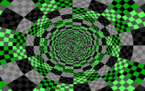
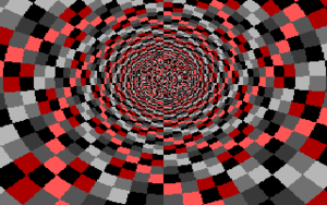
The "Tunnel"
Now let's add some features:
- extract angle as opposed to the distance and combine both
- reverse divide the distance to create the "tunnel" effect
- animate with smooth steps along the distance
- improve on the colors with subselecting from the standard palette
- quit the program on ESC
This results in the following program with a size of 63 bytes :
push 	0xa000 - 10 - 3 * 20	; video base - 3.5 lines
or 		al, 0x13				; mode 13h = 320 x 200 in 256 colors
pop 	es						; get aligned video memory base
int 	0x10					; switch videomode
X:
sub		dh, [si]				; vertical alignment
pusha							; push all registers on stack
fild 	word	[bx-9]			; fpustack :  x
fild 	word	[bx-8]			; fpustack :  y  x
fpatan							; fpustack :  arc
fst 	st1						; fpustack :  arc  arc
fcos							; fpustack :  cos(arc)  arc
fimul	dword	[si]			; fpustack :  l*cos(arc)  arc
fidiv	word	[bx-8]			; fpustack :  l*cos(arc)/x  arc
fiadd	word	[bp+si]			; fpustack :  l*cos(arc)/x+offset  arc
fistp	dword	[bx-7]			; fpustack :  arc
fimul	word	[byte si+val]	; fpustack :  scaled_arc
fistp	word	[bx-5]			; fpustack :  -
popa							; pop all registers from stack
xor 	al, cl					; XOR scaled_arc with distance
and 	al, 16 + 8 + 2			; sub selecting palette part
stosb							; writing to screen
mov 	ax, 0xCCCD				; Performing the famous
mul 	di						; Rrrola trick
jo 		X						; next frame check
add 	word [bp+si], byte 23	; change offset smoothly
in 		al, 0x60				; check for ...
dec 	ax						; ...ESC key
jnz 	X						; otherwise continue
ret								; quit program
val:	dw 6519 				; n = 160 * 256 / pi / 2 ; 0x1977
Many other tiny tunnel effects have been coded, so it is highly recommended to check out the documented source code of "Constant Evolution" by ryg/Farbrausch and the "Heart shaped tunnel" from Lord Kelvin, both with a size of 64 bytes. While "Constant Evolution" takes a slightly different route than the example here (classic FPU communication, classic X Y construction, sqrt(x²+y²) instead of using fcos+fimul), "Heart shaped tunnel" uses no FPU at all.
The takeaways from this example are:
- Loading a constant from the code with some degrees of freedom
fimul dword [si] multiplies with a 32 bit integer dividend for the tunnel effect. The highest byte of this constant points to our code, to the opcode from or al, 0x13. This instruction puts 0x13 into al, and since there a lot of possibilities to achieve this, there is a direct way of changing the appearance of the tunnel with changing this instruction to one of the following : mov al,0x13, add al,0x13, xor al,0x13, adc al,0x13, sbb al,0xED or sub al,0xED. In this special case, the instruction can also be swapped with pop es to gain a further degree of freedom.
- normal loading of a constant which can't be reused as opcode
Although it's the ultimate goal to not even use a single extra byte for constants, sometimes the required sequence simply does not appear in the code. In this case, a constant is needed to convert the angle from the range [-pi,pi] to the color space in a way that no gaps appear while stepping from 359° to 0°. In the last line at val: the value 160 in the comment is 32 * 5 where 5 is number of "spiral arms" the tunnel effect has. The 8bit shift (*256) is to increase precision. It turns out that 16bit precision is enough to get a decent "gap closer" for values obtained by fpatan.
- operating directly on an indirect memory location without offset
The location [bp+si] is used as animation variable, while both participatory registers are kept fixed (the value is 0x0A?? and therefor way above our code). Since we work with 16bit values and the top 8bit are the measurement in pixels, the instruction add word [bp+si], byte 23 allows for sub pixel precision in animation, while occupying 3 bytes of space. Depending on the target hardware, this value 23 can be increased/decreased to achieve faster/smoother animation.
- Optimizing the check for the next frame
Normally, there is a check like test di,di with direct consecutive branch necessary. The used approach allows for direct branching after mul di with jo, since the overflow flag is always but twice triggered for a frame. This saves two bytes, but also requires adjustment of the animation constant, because the animation constant is also added twice. A further benefit is that in one of these two cases, AX is zero which save a further byte on the following ESC check (dec ax instead of dec al )
Size optimizing the "Tunnel"
Now if we abandon all the comfort, alignment, smoothness and convenience, and optimize this straight for size, we end up with a 52 byte version. This does not include the possible exclusion of color tuning (2 bytes), after all the effect is supposed to look at least somewhat appealing ;)
mov		al,0x13				; mode 13h = 320 x 200 in 256 colors
int		0x10				; switch videomode
X:
or		al, [bp+si]			; *illusion* - executed ONCE
xor		al, 0x68			; *illusion* - executed ONCE
mov		dx, 0x79F			; *illusion* - executed ONCE
pusha						; push all registers on stack
fild 	word	[bx-9]		; x
fild 	word	[bx-8]		; y x
fpatan						; arc
fst 	st1					; arc arc
fcos						; cos(arc) arc
fimul	dword	[si]		; l*cos(arc) arc
fidiv	word	[bx-8]		; l*cos(arc)/x arc
fistp	dword	[bx-4]		; arc
fimul	word	[bx]		; scaled_arc
fistp	word	[bx-5]		; -
popa						; pop all registers from stack
sub		ah, [bp+si]			; animation along distance
xor		al, ah				; XOR scaled_arc with distance
and		al, 16 + 8 + 4		; sub palette selection
stosb						; write to screen, advance DI
mov		ax, 0xCCCD			; the famous
mul		di					; Rrrola trick
jmp 	short X-1			; *ODD* jump into "int 0x10"
Since this code contains an "odd jump" into the middle of the instruction int 0x10 it helps to disassemble the code from address 0x103 on, until both code pathes realign at pusha :
adc 	[bp+si],cl		; decrement framecounter
add 	dh,[si]			; vertical alignment
push 	word 0x9FBA		; video base - 3.5 lines
pop 	es				; get aligned video memory
						; continues with "pusha"
Like before the mul di instruction triggers the overflow flag - and the carry flag - always but twice per frame. CL remains 0xFF unchanged from start, so adc [bp+si],cl effectively decrements the framecounter twice per frame.
The dividend for scaling the arc is now taken from the location [bx], which is 0x20CD. Calculating the number of "spirals" backwards from this number (*pi*2/256/32) gives about 6.44 which is close enough to 6.5, so that the visual gap in the top is almost not recognizable - besides from the miscoloring which can be fixed by removing the 16 from and al, 16 + 8 + 4.
It's noteworthy that the location [si] does not contain a good offset anymore, since push <word> moved away from the top, to help create *illusion* code that not only realigns soon in the second code path but also does not modify registers and memory environment in a hindering way (only AL and DX are modified)
The takeaway here is to study the modbytes of instructions that are very likely to appear in tiny intros, as well as using their constants as code. int 0x10 will almost always be in your code, so there is always adc byte[??], 8bit_reg too in between.
Finally, you might have noticed that these tunnels don't "spin". For the cost of two bytes this can be easily added. add al, [bp+si] before applying XOR in the last example would offset the arc with the framecounter and produce a spinning effect. For a coherent visual experience the sub palette selection must be changed to and al, 8 + 4, too.
FPU Tricks
Comparing 2 float numbers on the FPU Sometimes when doing fpu algabra, you need to compare 2 float numbers using the FPU (for example when calculating an intersection between a point and an object).
To do so will take a few steps:
fcomp      ; compare the contents of ST0 and ST1
fstsw ax   ; copy the fpu flags to ax (ah)
sahf       ; copy the contens of AH register to the CPU-flags
jb inside  ; you can now check the cpu flags and jump accordingly


